
Tensile Test Experiment
Introduction
A tensile test is one of the most fundamental mechanical tests used to determine the behaviour of a material when subjected to an axial tensile load. During the test, a standard specimen is gradually pulled until it deforms and eventually fractures.
The tensile test provides important information about the strength, stiffness, ductility, and deformation characteristics of engineering materials. These properties are essential for material selection and structural design.
The experiment is commonly performed using a Universal Testing Machine (UTM), which applies a controlled tensile force while measuring the corresponding elongation of the specimen.
Physical Concept
When a material is subjected to an axial tensile force, equal and opposite forces act along the longitudinal axis of the specimen. These external forces create internal resisting forces that are distributed over the cross-sectional area of the specimen, producing tensile stress.
As the applied load increases, the specimen elongates and experiences tensile strain. Initially, the material behaves elastically and returns to its original dimensions when the load is removed. Beyond the elastic limit, permanent (plastic) deformation begins, and continued loading eventually causes fracture.
The tensile test studies this complete load–deformation behaviour and provides the stress–strain relationship of the material.
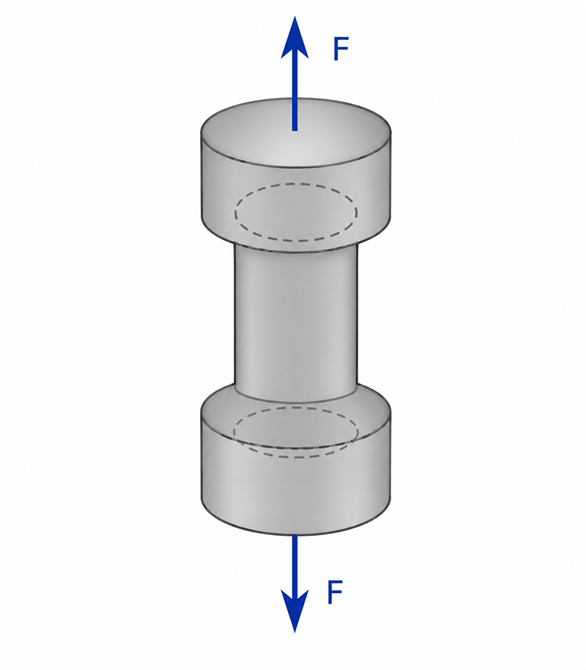
Figure 1. Concept of axial tensile loading acting on a specimen.
Equal and opposite axial forces produce tensile stress within the specimen, causing it to elongate. In the actual experiment, the specimen is held between the grips of a Universal Testing Machine (UTM), which applies these tensile forces in a controlled manner.
Everyday Intuition
Many objects around us experience tensile loading in daily life.
Examples include:
- Suspension bridge cables supporting traffic loads.
- Crane ropes lifting heavy loads.
- Reinforcement bars resisting tensile forces in concrete structures.
- Steel wires used in elevators.
In each case, the material must safely withstand tensile forces without failure.
Experimental Relevance
The tensile test is performed to determine the mechanical properties of engineering materials and evaluate their suitability for practical applications.
The test helps determine:
- Young's Modulus
- Yield Strength
- Ultimate Tensile Strength (UTS)
- Percentage Elongation
- Percentage Reduction in Area
- Ductility
These properties are widely used in the design of buildings, bridges, machine components, pressure vessels, and other structural systems.
Apparatus and Working Principle
The experiment is performed using a Universal Testing Machine (UTM).
The major components are:
- Loading frame
- Fixed grip
- Movable grip
- Load measuring system
- Extensometer or dial gauge
- Control panel
A standard specimen is securely gripped between the machine jaws. A gradually increasing tensile load is applied while the corresponding elongation is measured. The collected data are used to construct the engineering stress–strain curve of the material.
Mathematical Formulation
Stress
Stress is defined as the applied load divided by the original cross-sectional area.
where
- = Stress (N/mm² or MPa)
- = Applied load (N)
- = Original cross-sectional area (mm²)
Strain
Strain is the ratio of change in length to the original gauge length.
where
- = Strain
- = Extension of the specimen
- = Original gauge length
Strain is a dimensionless quantity.
Young's Modulus
Within the elastic region, stress is directly proportional to strain according to Hooke's Law.
Therefore,
where
- = Young's Modulus (N/mm² or GPa)
Young's Modulus represents the stiffness of the material.
Stress–Strain Behaviour
The engineering stress–strain curve obtained during a tensile test represents the complete mechanical behaviour of a material under tensile loading. It identifies the different stages of deformation and helps determine important mechanical properties such as the proportional limit, elastic limit, yield strength, ultimate tensile strength, and fracture point.
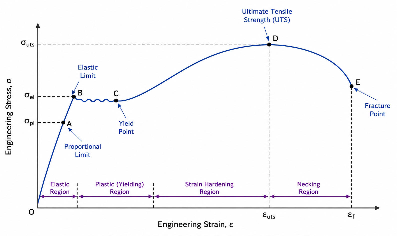
Figure 2. Typical engineering stress–strain curve for a ductile material (e.g., mild steel).
Proportional Region
Stress is directly proportional to strain and Hooke's Law is valid.
Elastic Region
The material returns to its original dimensions after unloading.
Yield Point
Plastic deformation begins and permanent deformation occurs.
Strain Hardening Region
Additional stress is required to continue plastic deformation.
Ultimate Tensile Strength (UTS)
The maximum engineering stress attained during the test.
Necking Region
Localized reduction in cross-sectional area occurs.
Fracture Point
The specimen breaks and the test ends.
Ductile and Brittle Materials
Ductile Materials
Examples
- Mild Steel
- Aluminium
- Copper
Characteristics
- Significant plastic deformation before fracture.
- Large percentage elongation.
- Distinct yielding behaviour.
Brittle Materials
Examples
- Cast Iron
- Concrete
- Glass
Characteristics
- Very little plastic deformation.
- Sudden fracture.
- No pronounced yielding region.
Engineering Significance
Tensile testing is one of the most important material characterization methods used in engineering practice.
The results of a tensile test help engineers:
- Select suitable construction materials.
- Predict structural performance.
- Establish allowable design stresses.
- Compare material quality.
- Verify compliance with engineering standards.
Therefore, tensile testing forms the basis for the safe and economical design of structural and mechanical systems.